
-Guaranteed Horsepower
-Aerodynamically engineered non-metallic rotationally molded tube for lower air temperature and less intake sound
-Engineered to specific vehicle design
-Easy to Install, usually in 90 minutes or less!
-Lasts up to 100,000 miles before service is required (depending on driving conditions)
-Available for many popular automotive applications
-K&N Million Mile Limited Warranty®
Price: $350
toptuned@hotmail.com
www.toptuned.blogspot.com
toptuned@hotmail.com
www.toptuned.blogspot.com
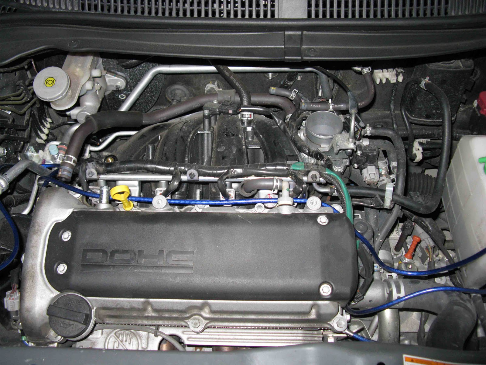
Before


After
*-*-*-*-*-*-*-*-*-*-*-*-*-*-*-*-*-*-*-*-*
1.) Disconnect the negative terminal from the vehicle battery.
2.) Pull the plastic engine cover from its mounts & remove from the vehicle. (Fig. 1)
3.) Remove the bolt securing the air box feed pipe to the slam panel. (Fig 2)
4.) The 4 bolts securing the air box assembly to the engine as shown. (Fig. 3, 4 & 5)
5.) Unclip the intake hose from the throttle body as shown. (Fig. 6)
6.) Carefully lift the air box assembly off the throttle body & move the assembly forward to gain access to the vacuum solenoid switch & MAS (Mass Air Sensor). Unbolt & remove the vacuum solenoid switch & unclip the electrical harness plug from the MAS. (Fig. 7 & 8)
7.) Carefully remove the complete air box assembly from the vehicle. (Fig. 9)
8.) Replace the upper vacuum solenoid hose with the longer supplied hose & secure with the original clamps. Secure the vacuum solenoid switch to the threaded hole on the rear of the manifold using the original securing bolt. (Fig. 10 & 11)
9.) Assemble the saddle bracket / mounting bracket using the allen head bolt, nylon conical washer, flat metal washer & nylock nut. (Fig. 12)
10.) Fit the mounting bracket assembly to the original air box mounting point & secure using the original bolt. (Fig. 13)
11.) Unscrew & carefully remove the MAS from the air box assembly. (Fig. 14)
12.) Carefully fit the MAS to the supplied MAS adaptor tube & secure using the screws supplied. (Fig 15)
13.) Secure the air filter to the MAS adaptor tube using the hose clamp supplied. (Fig. 16)
14.) Unclip & remove the intake hose from the air box assembly & refit the hose to the throttle body. (Fig. 17 & 18)
15.) Place the original hose clamp around both the saddle bracket & intake hose. Do not fully tighten at this time. (Fig. 19)
16.) Fit the air filter / MAS adaptor tube assembly to the original intake hose & now tighten the hose clamp. (Fig. 20 & 21)
17.) Reconnect the electrical harness plug to the MAS. (Fig. 22)
18.) Carefully expand the flexi cold air hose. Feed the hose down to the lower spoiler & secure using the plastic tie supplied. (Fig. 23)
19.) Position the other end of the hose to finish approx. 4” / 10cm from the air filter & secure using the plastic tie supplied. (Fig. 24)
20.) Refit the two previously removed long air box securing bolts to the threaded holes on the engine. Refit the engine cover ensuring that the cold air hose fits under the cover. (Fig. 25)
21.) Reconnect the negative battery terminal.
22.) Carry out a final check of the height / alignment of the K&N induction system before starting the engine. Installation is now complete. (Fig. 26)


So easy to install, and the results are great. There's nothing better than K&N.
ReplyDelete